Hexacopter

It all started when Doug Radford forwarded an email with this link http://mikrokopter.de/ucwiki/VideoAbspielen?id=188.

The link points to a German web site with a video demonstrating a Hexacopter. Doug's interest was aroused and, as the website is mostly in German, he asked for some German - English translation from yours truly.

The more I started reading, the more I got interested and the link to the shop became increasingly tempting. The only problem was that the price level in Germany is somewhat different from the Chinese benchmark we are used to...but after a few days of hesitation I had a weak moment and started clicking. A week later an almost empty box arrived....

imag0017 

I was lucky that my flatmate Andy was fascinated by the Hexacopter as well and offered to build the frame. So instead of spending $200 on some aluminium pieces, I ordered the electronics from Germany and the frame parts came from our local hi-tech supplier - Bunnings.

Many hours later (I think Andy underestimated the work required!) a new creature was born....

imag0027

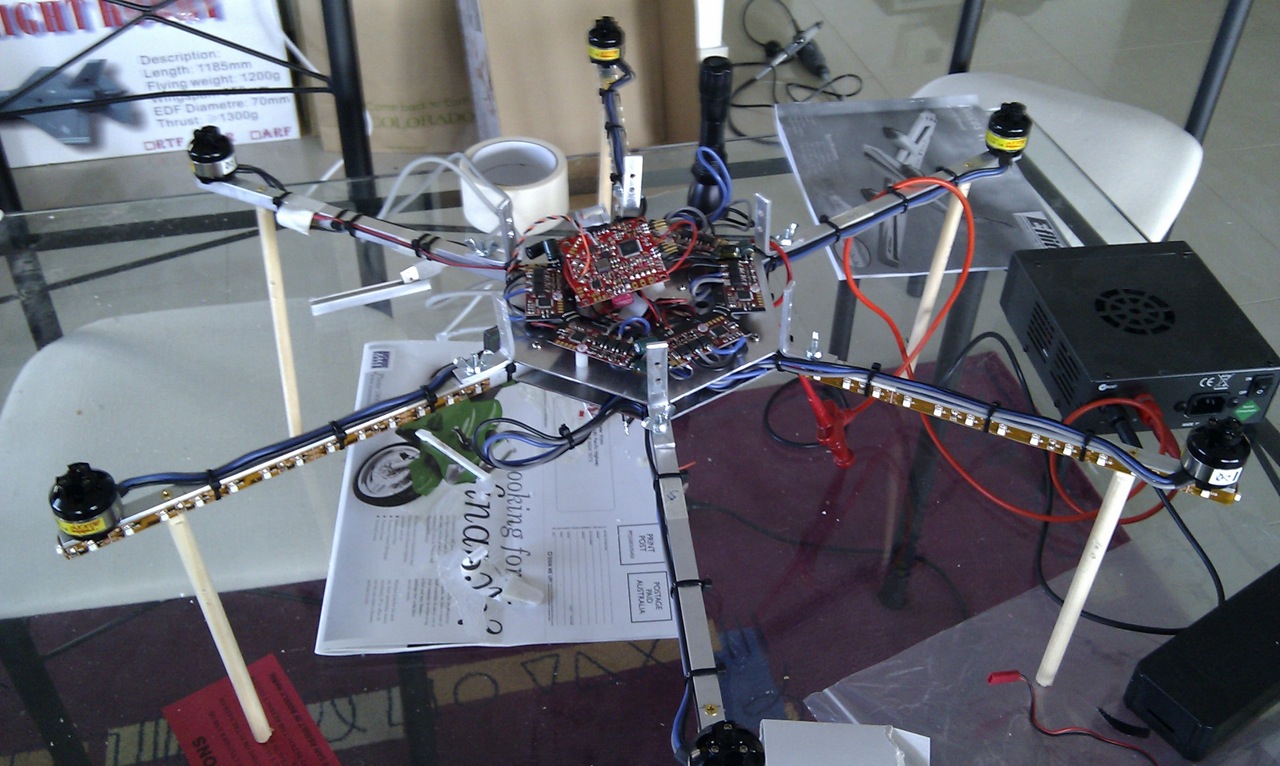
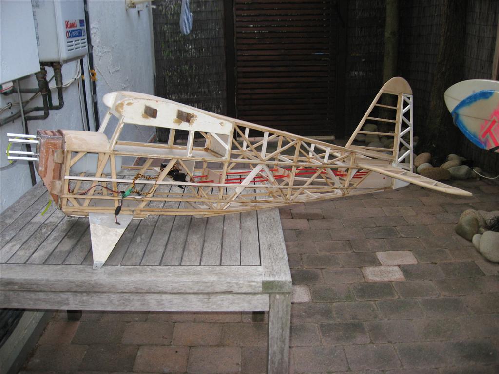
As you can see, building a Hexacopter has not much in common with building a Hurricane. A Hexacopter consists of 6 aluminium profiles with a motor on the end, a baseplate in the middle which holds everything together and a lot of electronics.

There are 6 speed controllers (each motor needs its own controller) and in the middle is the main flight control board.

imag0028

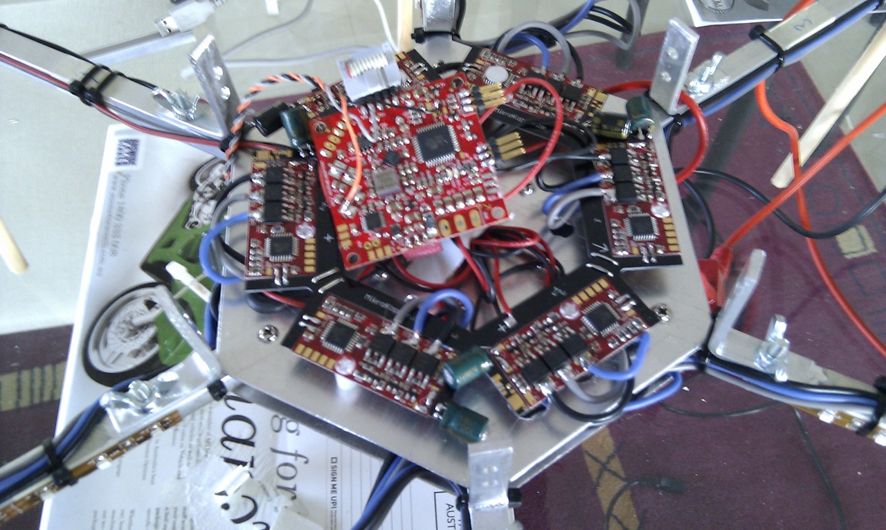
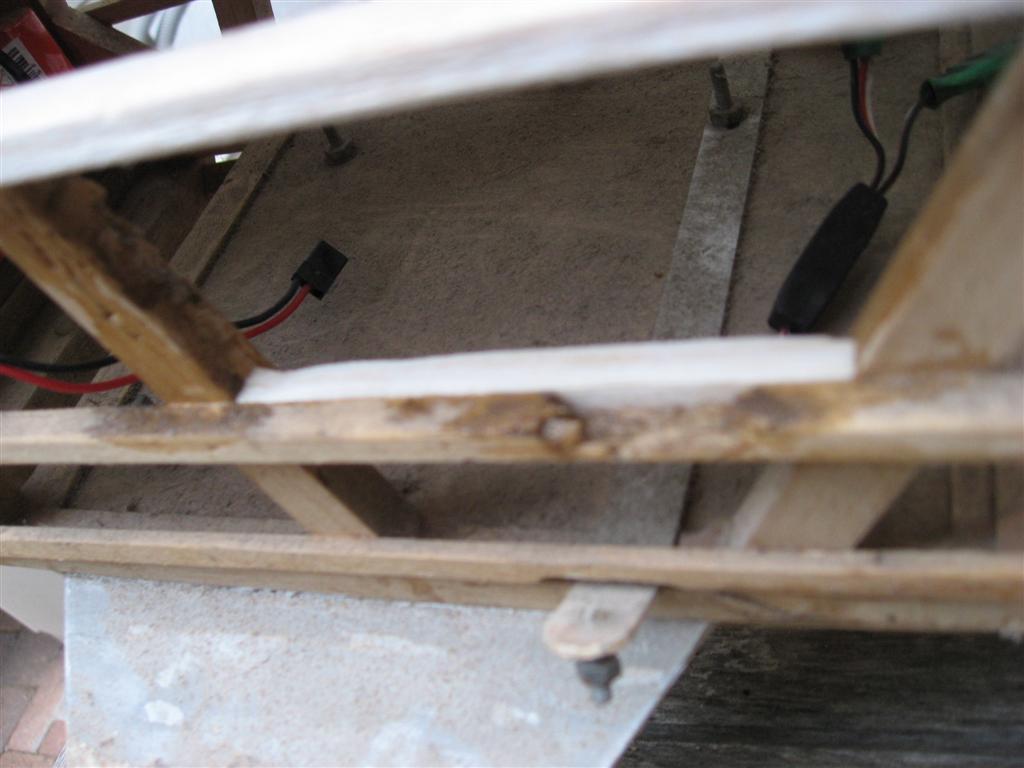
Work hasn't quite finished in this picture but clearly visible is the amount of soldering required. In fact, all the boards require the soldering on of some additional components and then comes all the connections to the speed controllers and motors. The 6 smaller boards on the picture are the speed controllers and the one in the middle the flight controller.

The Hexacopter has no moving parts apart from the motors but all motors are mounted fixed. So how on earth does it fly?

It all works with some smart software which varies the speed of each motor as required.

  • opposite props are counter-rotating to eliminate the rotational forces
  • for moving forward the rear motor speed is increased and the Hexacopter is, thus, tilted slightly forward
  • for moving backwards the front motor speed is increased and this tilts the Hexacopter backwards
  • same principle applies for moving to the right and left
  • rotating (on the spot) is achieved by creating a speed difference between opposite motors (rotating clockwise -> increase speed of left and right props and lower speed of front and rear props)

The speed controllers are not quite the usual cheapo version either. A normal ESC, as we all know, is controlled by PWM signals from the receiver. Updates from the receiver to the ESC are done 50 times per second and while this seems rather fast, it is not fast enough for the Hexacopter. The 6 special ESCs are connected via I2C bus and are updated 500 times/sec (each)!

The flight control board contains an AVR Atmel microprocessor, 3 gyros, a height (pressure) sensor, a 3-axis acceleration sensor and a few more bits and pieces.

And as we already have a powerful microprocessor on board we don't need a normal receiver either. Instead we take a Spektrum remote receiver and solder the wires directly onto the flight controller board. The flight controller talks directly to the remote receiver and decodes the signals recieved, no normal main receiver required. (On the picture above the twisted wires from the top go to the receiver.)

As you would expect, instead of setting up aileron and elevator thows the Hexacopter is setup via computer and the special Microkopter tool which is available from the developer's web site.

Setup itself is reasonably easy if you go for the default settings but there are many, many, parameters to play with if you want to optimise and customise the behaviour.

Power is supplied by a normal LiPo. Either 3 cell or 4 cell can be used. I used a 4s 4000mAh as this was what I had available. Alll 6 motors are supplied by the single battery but luckily the motors are quite small only drawing 10-12A max. But still, this adds up to >60A for full power.


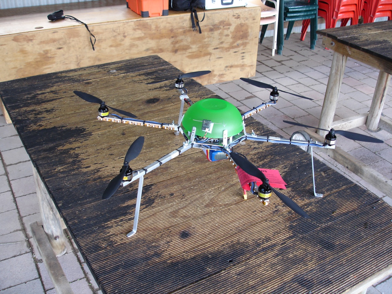
Here is the completed Hexacopter. The green "canopy" comes from Coles (it looks suspiciously like Pete has been going to Tupperware parties - Ed) and some bright red and blue LEDs have been added to help orientation. Without some visual aid it is difficult to see the orientation with a symetrical design like this.

dsc00509


And the all important question -- how does it fly???

In one word - excellent!

It flies similar to a heli but the self-stabilisation functions level it out automatically and make it a fair bit easier to fly than a normal heli. It is capable of rolls and loops however sustained inverted flight is not possible as there is no pitch control.

All the little electronic helpers can be adjusted and disabled if desired but at least in the "beginner" mode it is very easy to handle.

Here the video from the maiden flight.

{flv img="Hexa.jpg" showstop="true" width="960" height="540"}Hexacopter{/flv}


What next?

There is certainly more to come.

First will be the navigation controller (already on it's way from Germany!) which adds GPS navigation. This allows autonomous flights, position hold and "coming home" functionality.

The Hexacopter is obviously an ideal platform for photo and video work and the camera mount is already in the planning stage. Soon we should get some great video from high up....

And then there is still the possibility of MKII. The software can handle different configurations. So from a light-weight 4 motor racer to a 12 motor monster everything is possible Cool


Link: http://www.mikrokopter.de


Peter Wyss

There's been talk of a one make fun competition over the last year or two, ever since the Plagiarist (the previous one-make model of choice) went out of production. More on this topic to be written elsewhere, but I thought I'd give one of the options a try.

I've noticed a lot of people flying the Phoenix Scanner over the past few years. A low wing "trainer" style of aircraft, ideal for a 40-something glow motor and 4 channel control. Without exception, everyone seemed to like the scanner, and Neil Waterhouse has been flying the skin off his for a very long time (I now know that he is currently flying the skin off his 3rd Scanner - he likes them that much).

Here's an image of the Scanner - courtesy of Duane's Planes - one of the places where you can get a Scanner. She ain't pretty, but she makes up for it in other ways - read on:

phnscanner

So I picked up Scanner from Hobbyland in Hornsby (on impulse, I was there to buy piano wire) for the princely sum of $127, and set about building it...

...which didn't take long at all. The aircraft is pretty much fully assembled, the control surfaces are all hinged and fitted, with all hinges pinned very neatly. The engine mount is pre-installed, with lock washers on the fittings, and the firewall has a sponge ring on the inside of the aircraft for the tank to push against to help prevent vibration, to mount the tank firmly and to stop it sliding forward and creasing the pipes. 

The tail went in very smoothly, the film covering is very good, and the component fit is excellent (no wrestling with the wing halves to get them to join perfectly - they were made for each other). The control horns supplied are of good quality, and the only parts that I replaced were the plastic clevises - I prefer to use metal ones. 

The aircraft needs 4 servos - one each for elevator, rudder, aileron and throttle. I used standard servos for aileron and rudder, a mini servo with metal gears for throttle, a HiTec HS645MG (metal gear) for the single aileron servo (this is the only design weakness, in my view - I dislike single servos for aileron control and would have modified the model to take 2 aileron servos if I wasn't trying to keep it as standard as I could).

The undercarriage is a tricycle set up. The legs go into slots in a hardwood bearer in each wing, and go up into a snug fitting hole to keep them straight. I always use a soft setting glue in the slots to help the legs (my preference is a foaming glue that fills the space and gives them a buffer).

The steerable nose wheel was good quality, and I did use an extra servo here as I figured my Scanner would do a lot of landings and I don't like risking the stress from the nosewheel on the gears of the rudder servo - so despite wanting to keep standard, I decided to bend my own rules. I used a servo-saver technique that I'd read about, using a couple of bits of soft tube...here's an image (using springs), again courtesy of Duane's Planes, where you can buy the DuBro version of this. Really neat:

DUB120

I used a Sanyo Eneloop XX 5 call battery pack - 2500mah, or over 4 times what the original RX packs used to hold - and checked over all the glue joints etc as I assembled the plane. Mighty impressive - great quality all the way through and the sort of build and finish that I'd expect from a MUCH more expensive aircraft. I'm a fan of Phoenix planes anyway, and this one is top of the tree. I did brush in a bit of 5 min epoxy in a few places (firewall, the ply holding the wingnuts etc), but I suspect I could have left it how it came, with no ill effects.

For a motor, I used a very old OS46AX that I acquired 2nd hand several years ago in a badly thought-out trash and treasure purchase. I had to fit a bush-find OS silencer as the original purchase had a home made in-cowl silencer, and I used a Bolly 11X6 carbon propellor.

So, off to the field. Radio check, fuel in and the old OS burst into life despite having lost any last vestiges of compression many flights ago. I set her off slightly rich, ground handling was superb, take-off was easy, and a couple of clicks of down elevator, left aileron and one click of right rudder and she was flying beautifully. 

So the maiden flight continued with inverted, rolls, loops, a few high G spinny/rolly things, lots of high speed passes (this thing is really quick - not a trainewr on full throttle, even on a tired old motor) and a nice gentle landing to follow. 

Following a quick checkover, to make sure all was still tight and working as planned, she was fuelled and sent up again, for another 10 minutes of hooning, then a landing, absolutely no vices discovered, a joy to fly so...then more fuel, then a takeoff and then...

Kelvin and I were the onyy two people in the air. He was flying something fairly quick with an OS55 on a 12X5 prop, and it was clearly essential that we raced a few circuits to find out which aircraft/motor/prop was quickest. Egged-on by the front row audience in the geri shed, Kel and I raced closer and closer, turning tight, swapping the lead...

...until we "touched" the aircraft over the bush. The Scanner span straight in, and Kel landed his aircraft with significant damage (not least the undercarriage, which gave up as soon as it felt earth beneath it). The Scanner had found hard rock and a metal pole to cushion the plummet, and was destroyed - well beyond repair. Kel's aircraft might be repairable, but might not look quite as pretty afterwards. The chorus line in the geri shed sang, as one - "It was only a matter of time, I could see it coming, when will you young hooligans learn". 

A very sad end to my Scanner. It took Kel and I a long time to stop laughing though, and we brought a little frivolity to the serious business of flying RC. I'm $127 and about 3 hours of building time down - and I'm going straight out to buy another Scanner. Bloody brilliant - I won't be without one of these in my shed!

Stan has completed the rebuild of the P40, in plenty of time for scale day in May 2015. Click HERE to read the story.

Here's part 9 of Stan's build story. Essential reading for scale builders! Download [HERE]

This is the first of a planned (brief) series on the salvage of a Rearwin Speedster - one of these chaps:

spe001

The wiki page on the Speedster is HERE and it tells me that there were only about 14 of these single seaters ever built - around 1930 onwards.

But I'm getting ahead of myself...

...I love the trash and treasure evening, but this year had vowed not to buy any unwanted airframes, after some VERY mixed results when I did so in previous years. I was doing well until the end of the evening, when Mr David Pound, who hadn't secured a single bidder for a largish heap of scrap balsa framing and plastic bag, pleaded with me to make him an offer to avoid him loading the remnants back into his car. I reached into my pocket, had 65 cents in change (I wasn't splitting a note for this) and the deal was done. I have no idea, yet, which one of us was the Patsie in this transaction. He seemed unusually happy to have cleared some space in his workshop though!

What I had purchased was a quarter scale (ie 8 foot wingspan in old money) airframe of a Speedster that appeared to have flown and, certainly, had been finished, covered, and subsequently stripped for repair. I think it was originally from a kit, built by someone with an eye for detail and very good building skills, had passed through several pairs of hands, before being stowed in Dave's garage. Rough assembly gives me a plump little aircraft with 96 inch span which, next to my 84 inch Cub, has the appearance of a lifetime spent eating too many pies. The Cub isn't, exactly, streamlined, but it looks like a racing snake next the the Speedster.

On closer examination (and it took me a few days to pluck up courage), the tail was broken off, the rudder was missing, there was quite a lot of damage to the frame, wings etc, and a nasty case of, well, woodworm?

If this was what you picked up after a crash at the field, there is no way on earth you'd be trying to rebuild it. So why am I? (There isn't a right answer here - by the way.)

Anyway, the wonders of thin CA had the old girl back into alignment, and I set about replacing, strengthening and a little bit of modifying. I'm using a range of glues on this. The old wood is VERY dry, which means that I need to use glues that will adhere and flex, so there is some PVA, some epoxy (varying drying times), some CA, and quite a bit of light strengthening going on.

img_1040 largeimg_1043 large

She appeared to have had a single elevator servo working the elevator (two parts joined by a hardwood beam) but, given she'll weigh 7kg or thereabouts, I have set it up to have a servo dealing with each elevator surface, one for rudder (all these Hitec 645s with metal gears). No problem fitting them in!

img_1044 large

and I'll also be putting a strong metal gear servo on each aileron (it appeared that she might, originally, have had a different setup - but installing two, now, is easy). Throttle will be a standard servo, and another for choke (plus, maybe, one for ignition).

The motor will be a 26cc petrol - RCG - with a 4.8 volt battery upfront to power the spark, and a large 6 volt battery pack behind the firewall to power the radio gear. I've chosen this motor because, although on the gentle side for a model of this scale, some of the original full size examples flew on little 70 horsepower units, and I do want to keep things looking real.

I've pushed out the motor by 5.5cms (to fit with the cowl - mercifully repairable), keeping the standoffs as short as possible and building a new ply box to hold it - glued and screwed, then taped and "painted" with epoxy down all edges. The motor was fitted to the standoffs, then the whole lot to the ply plate, then the motor removed - apparently this avoids putting alignment strain on the crankcase.

img_1041 large

The tank has just gone in, as has the cockpit liner and the control rod outers (supported, often, down the long fuselage), and I am getting closer to the sanding stage for the fuselage. 

A new rudder has been made and hinged (all hinges are also pinned with cocktail sticks prior to covering).

img_1042 large

When I get to the wings, I'll be adding in some extra strength with aluminium tubes (inners and outers) through the upper fuselage and into each wing. You'll see that the current setup relies on small hardwood stubs and then some underwing struts which will need to be very functional. Now I'm not an expert on this sort of thing, but I reckon this type of airframe would need to be capable of handling at least 6G, even if only in emergencies. That equates to a load of about 42kg (ie the weight of a small adult spread over the wings) which, by my reckoning, is more than the little stubs and struts should be asked to deal with. I'm not planning to subject this thing to 6G manoeuvres, but I do want to know that it is strong enough to get out of trouble, without adding too much weight, if it ends up upside down or in a spin.

Col Buckley is amazed that anything has risen from the original pile of bits (I should have taken some photos) and reckons the finished thing will be a "beautiful show pony" and, for my flying preferences "as boring as bats@&t". I'll be happy if she flies, but I reckon the boring bit might just be too true!

There's a lot of time to go into this, and it is a sobering thought that the 3 servos in the fuselage cost more than 200 times the cost of the airframe. The covering material will be a pricey one too, so the 65 cents, on a whim, might still hurt me, but it's nice to get back to some proper building and, with luck, she'll fly at the Autumn Scale Day.

And the woodworm? Dave has a feathery bird, by all accounts, that likes pecking balsa. Here's an example, now filled with glue and reinforced.

img_1046 large

I reckon Dave can keep his pecker to himself!

The good thing is that this is a BIG fuselage - easy to add repair sections, get my hands in to fit things etc.

Part 2 - wings, trial assembly, etc, to follow in the fullness of time. I'll also cover the large model inspection process (although I do intend to keep things light) once Dave has got over the above comment, given he'll be inspecting the Speedster.

Clive

Part 4 of Mike's Scooter build story is ready for reading. Click HERE to download it.

Mike Minty has been balsa bashing on a 3 bob plan, and building something rather nice.

Download part 1 of his build article [here] - where he talks about wood, and gluing, and other arcane arts!

Ed

Austar’s Fieseler Storch

I needed another back-up for Scale events as my well-worn 84” Spacewalker was getting a bit shy in lifting her skirts in performing set maneuvers.

Going over to Austar’s premises at Prestons near Liverpool, I came away with the Fieseler Storch ARF for engines from 20-26cc. This STOL aircraft became quite famous in WW11 as a reconnaissance aircraft as well as rescuing Mussolini from his castle when the Allies were closing in. At first glance it’s an ugly looking machine with its forward pointing undercarriage, large tail and long nose. However, after a time, she becomes quite beautiful as the build progresses.


The Storch is a high wing tail dragger, single engine, 96” span aircraft and I elected to power her with the 26cc Turnigy petrol two stroke.

Opening the sturdy cardboard box from Austar, I was disappointed to find scant, meager build directions, flimsy formers and some quite shoddy hardware. One of the wing tubes was missing and the covering, although drab olive, was bright and shiny. With a wipe of that wonder primer ESP followed by a spray of matt Estapol (courtesy of Doug Radford), our Storch now looked like a military aircraft.

I was warned this was one tail heavy machine and NOT to put the dual elevator servos down near the tail (as per directions) as this only exacerbated the problem. Little did I know it would eventually need nearly 2kg of lead up the sharp end!!

A non-standard leaf-spring tailwheel assembly aided steering and would take the bumps out of our grass field. 5 x standard Futaba 3001’s powered the throttle, ailerons and flaps. 3 x Hi-Tec 645MG servos worked the pull-pull rudder and split elevator. With the addition of an extra servo tray, the elevator servos were secured in the cockpit area with dowels and 440 wires transferring the drive to the horizontal flying surfaces. Other than that the build was fairly straight forward.

Inside the cockpit, the bare white wood stood out like the proverbial “dogs” so a coat of drab was given to dull down the interior. To encourage forward CG, both ignition and flight batteries were installed hard up against the firewall as was the CDI unit. Fuel tank was cable tied inside the cockpit - forward of the CG. A choke extension rod was mounted on a bell crank that exited under the aircraft. There was nowhere to install switches so, with the addition of ply and balsa (with the kind help of Barry Campbell); a patch was fashioned on the port side to accommodate the dual switches.

Ignoring the supplied piddley screws, I used large wood screws to anchor the undercarriage as well as the support struts. Even this was not enough. A hard landing broke the U/C so it was glued back with support timber and the whole lot fibreglassed from the inside (Thanks Grant!!). The kits stiff, no-give U/C needs oleos which I will fit in due course.

To finish off (to avoid bounce), 4” Cub inflatable tyres replaced the hard rubber kit wheels.

Instruction sheet stated the CG was between 85-95mm from the leading edge. To accomplish at 95cm, 1.1kg of lead had to be added to the firewall to get her to balance. She was now ready for the maiden.

It was a clear day with a steady wind from the sea. After hours of fiddling to try (unsuccessfully) to get the engine to fully rev out, Tom Sparkes gave her throttle and she did a three point take off.

Her bum hung noticeably and Tom had to fight to keep control. Then – shock – horror. Over the western end of the field she just kept turning, entering into a right-hand, downward pointing barrel roll. Onlookers scattered at breakneck speed as the big German monoplane came hurtling towards them. Skillfully our ex-CFI pulled her out with just meters to spare.

Shaking like a jelly, Tom landed the Storch, sat down, wiped his brow and commented this was one very sick aeroplane. Heaps more weight was needed in the nose!!!

I took her home and wondered why this baby was so tail-weighty. Another half a kilo of lead was attached to the engine stand-offs with cable ties and wood screws. This brought the CG back to around 82cm (never trust the instructions) from the leading edge. I was now worried about all the weight (1.6kg of lead plus 890gms of engine) hanging off the firewall.

A few days later at the field, Tom Sparkes checked engine timing to see if top end performance could be improved. It was factory pre-set at 45 degrees BTDC. No wonder it ran rough. Adjusted to 28 degrees BTDC, the engine revved out fine and there were plenty of herbs in reserve.

Tom again took the controls and the Storch, with all the extra nose weight now raised her tail, ran on the mains and lifted gracefully into the air. After a few circuits, she came in for a spotless landing. Tom commented she was a different aeroplane, behaving like a puppy dog. My main problem was how to integrate all that temporary lead into the aircraft.

After plenty of discussion, Tom Sparkes kindly machined up four heavy and longer solid brass stand-offs as well as a brass spinner nut to replace the lightweight aluminium hardware. With the aid of Barry Campbell’s artistic eye, a thicker 5/16” plywood firewall was cut and glued onto the original. I lavished a heap of chopped fiberglass cloth and resin into the front of the aircraft to add both strength and weight to the firewall.

With all this extra weight and the engine sitting around 30mm further forward, I STILL had to fiberglass in another 130gms of lead into the cowl. She now balanced at 82cm.

A week later all was ready and it was my turn to fly the lady. After a few deep breaths I slid forward the go lever and the Storch ceremoniously lifted her tail, ran for a few meters then majestically climbed out. I ran my tongue round a very dry mouth. After a few completed circuits my breathing returned to near normal. She floated in wonderfully on finals with the aid of a little flap and gently touched down. After taxiing back to the pits and hitting the kill switch, I wiped the moisture from the transmitter then my hands. At long last, I now owned a very gracious and polite scale model which will now (hopefully!?) continue to eat out of my hand.

I would like to sincerely thank Tom Sparkes, Grant Furzer, Doug Radford, Ron Clark and Barry Campbell for their invaluable help in this project.

Col

Mr Minty has got his Scooter into the air. How did it fly? Click HERE to download the story.

Just a reminder that is the "autumn" glider day on Sunday 8th Feb - starting around 9:30am. 


There will be two events on the day - one for electric gliders, and the other for non-powered gliders launched from a bungee.

If you've taken part before, you'll know the ropes, but for those that have a glider but haven't taken part, this is a fun event - it is a competition but it is great fun to be part of, and you don't need a cutting-edge glider to be competitive. In the electric event, it's not unusual for a foam glider - Easy Star/Bixler etc, to do well, and for the bungeee event, some people just take the propellor off their electric glider, tape on a tow hook and give it a go. The event was won, a year or two ago, by one of these conversions, so it is as much about getting a good glide in the right air, with a bit of luck thrown in, as it is having the best thermal soarer and the experience to sniff out thermals. 

Register to read more...


.

Dont forget to have a look at our Facebook page for photos of Biplane day over the next few days.

Here is a sneak peek.

Mr Minty has got as far as part 5 of his build story. Download it by clicking HERE
For those of you wondering whether it is worth repairing a damaged ARF, Mr Minty managed to repair a very badly damaged Phoenix Tiger 3. Click HERE to download the story.

If you go to page 1 of members articles, HERE, you'll be able to download and read Stan's report on finishing the rebuild of his P40 - just uploaded. There are 7 pages of articles from members, 10 to a page, so a lot of good reading on some of the more complex and intricate builds, and some interesting models, as well as plenty of tips and ideas. All good light reading!

Ed

Mike has made it to bending and shaving stage. It happens to us all, at one time or another. Click HERE to download his latest episode in the build of this unusual aircraft.


Click HERE to download Stan's article for your reading pleasure.
Here's part 6 of Mike's Scooter build, which takes us all the way through the finishing process to the first flight. Compulsive reading - click HERE to open the PDF file.